Polski
 Čeština
 English
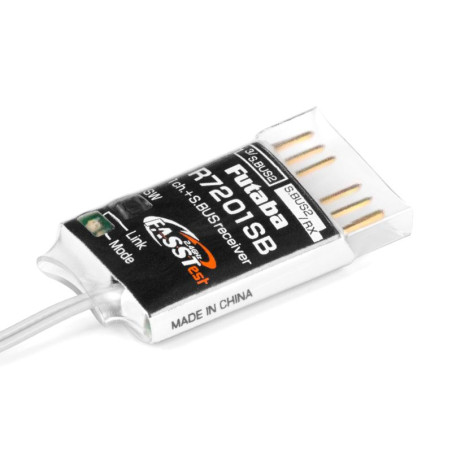


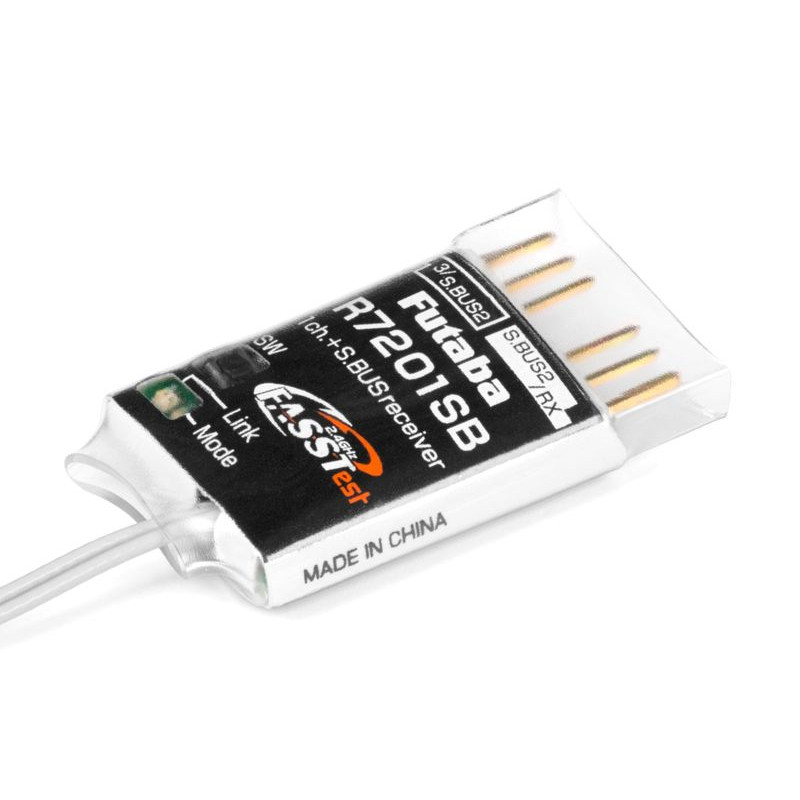
A small and very lightweight Futaba FASSTest 2.4 GHz transmission system telemetry receiver with a pair of full-range differential antennas. It is primarily designed for use in drones and other models using control units communicating via S.BUS or S.BUS2.; due to its compact size and very light weight, it is also suitable for small aircraft models with S.BUS/S.BUS2 servos and is ideal as a backup receiver for dual receiver operation with other FASSTest receivers. The R7201SB's optional router channel modes allow one slot to function as a classic PWM channel output (channel 3)/S.BUS2 or S.BUS port; the other slot functions as an S.BUS2 port or is used to connect a second receiver in dual-receiver operation. S.BUS2 port for bidirectional communication allows connection of S.BUS2 servers, telemetry sensors and other compatible devices. Receiver operating states are indicated by an LED.
Transmission system:
Futaba FASSTest-2.4 GHz with telemetry for flying models, FASSTest 26CH/18CH/12CH modes
Note that only digital servos can be used in the FASSTest 12CH high repetition rate mode.
Power supply:
3.7-7.4 V (nominal voltage), the operating voltage range is 3.5-8.4 V - that is, for example, 4-6 NiMH, 1-2S LiPo, 2S LiFe and Li-ion batteries, BEC power stabilizers within the voltage range.
Antenna:
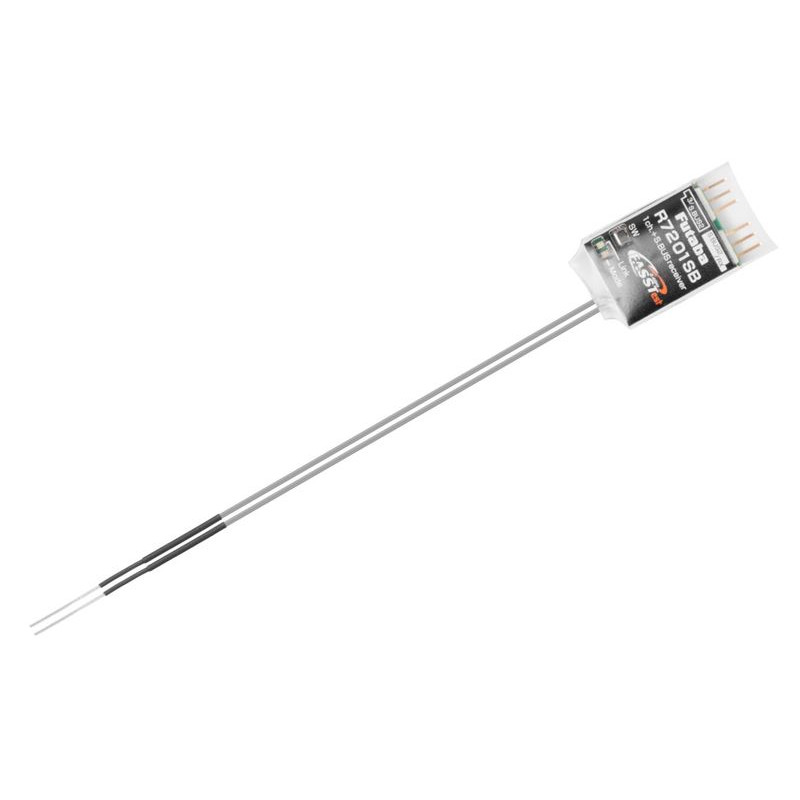
The receiver is equipped with a pair of differential antennas to maximize signal reception regardless of the relative position of the model and transmitter. They should be mounted on the model with a mutual orientation of 90°. The antennas are equipped with housings to improve the directional characteristics of the antennas.
Receiver outputs, channel modes:
The receiver is equipped with sockets for standard Futaba connectors (with a protrusion), into which, of course, UNI connectors (JR/Graupner, Hitec) without a side protrusion can also be inserted (be careful not to confuse the polarity).
Channel outputs (PWM/S.BUS): The R7201SB allows you to reassign channels, allowing you to use a combination of classic PWM output and S.BUS2 input/output or dual receiver operation (requires a Futaba transmitter that allows dual receiver operation) . Channel modes are selected using a button on the receiver in a special setup mode - channel modes cannot be changed in normal operation.
S.BUS2: The S.BUS2 socket allows the connection of servos, gyros and other compatible S.BUS2 devices, as well as the connection of Futaba telemetry sensors, whose data can be displayed on the transmitter.
Two-receiver operation with automaticbackup
A two-receiver mode with automatic backup can also be enabled on the receiver, which automatically switches from the main receiver to the backup (or vice versa) one of the receivers (a pair of R7201SBs or one R7201SB and a second FASSTest S.BUS2 receiver) ) in the event of a signal loss. The function is basically the same as the FDLS-1 backup system, but no additional hardware is needed.
Telemetry
R7201SB transmits receiver supply voltage data to the transmitter without connecting any sensors.
The R7201SB allows the use of all Futaba telemetry sensors and other sensors compatible with the S.BUS2 bus system with two-way communication.
What is S.BUS2/S.BUS:
S.BUS - Futaba's serial bus with unidirectional communication that allows control of servos, controllers, switches, gyroscopes and other compatible RC devices connected to a single output port of the S.BUS receiver.
S.BUS2 - Futaba's serial bus for bidirectional communication allowing (like S.BUS) control of servos, controllers, switches, gyroscopes and other compatible RC devices connected to a single output/input port of the S.BUS2 receiver. In addition, it allows you to connect telemetry sensors and send data from them through the receiver for display on the transmitter; from some servos, the S.BUS2 can send information about operating current, temperature or servo output lever angle to the transmitter.
Unlike classic RC kits, the S.BUS(2) system uses serial data communication to send control signals from the receiver to the servo, gyro or other device. This data includes commands such as "move channel 3 servo by 15 degrees, move channel 5 servo by 30 degrees" for many devices. S.BUS(2) devices only execute commands belonging to their own set channel. For this reason, it is possible to connect several servos to the same signal cable, setting and controlling them individually as needed. The servo identification code (ID) is used for this purpose. You can find the ID on a sticker on the servo box.
The S.BUS2 servo can be connected to the receiver's S.BUS2 and S.BUS ports. Its function is determined by setting the channel in the servo's memory (this is done using the programming interface of the Futaba transmitter, the SBC-1 programmer or the CIU-3 USB interface with the S-Link PC program - for some servos, the channel can only be set using the transmitter).
An S.BUS or S.BUS2 servo connected to the channel output of a classic receiver (PWM) works like a classic servo. Its movement is indicated by a signal in the channel of the receiver to which it is connected. The settings of programmable servo functions remain in effect.
Technical data:
*Follow the instruction manual included with the product.